Power factor is the ratio between the KW (Real power )and the KVA (Apparent power) drawn by an electrical load where the KW is the Real power and the KVA is the apparent load power
It is a measure of how effectively the current is being converted into useful output work and more particularly it is a good indicator of the effect of the load current on the efficiency of the power system.
Current flow always causes power loss both in the supply and distribution system. A load with a power factor of 1.0 results in efficient loading of the power system. A load with a power factor of 0.8, results in much higher losses in the power system and a higher bill for the consumer.
Comparatively small improvement in power factor can bring about a significant reduction in losses, since losses are proportional to the square of the current. Reactive power is necessary to provide a magnetizing field required by motors and other inductive loads to perform their desired functions. Reactive power is an extra burden on the electricity supply system and on the consumer’s bill.
A poor power factor is usually the result of a significant phase difference between the voltage and current at the load terminals. This is due to Inductive load such as an induction motor, a power transformer, and ballast in a luminary, a welding set or an induction furnace, which results in ‘lagging power factor’ i.e. wastage of energy. 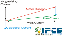
The simple solution to maintain the power factor in required range is to connect or disconnect the power factor correction capacitors.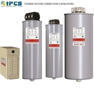
There are three methods of connecting the capacitor with the load
Fixed Capacitor Connection
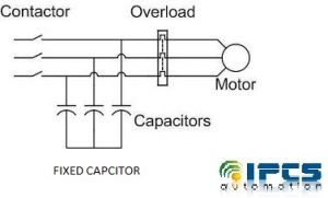
Fixed Capacitor is simple arrangement here capacitors will be connected permanently with the supply, but power factor cannot be maintained as precise as we want.
Manual switching
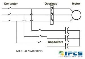
In manual switching, we need manually switch the capacitors to the supply by measuring power factors values. Manual switching is just impossible for rapidly fluctuating loads
Automatic switching
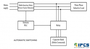
In automatic control system continuously monitors the power factor and make appropriate corrections to maintain it within the required range. In auto switching we will be using a power factor measuring equipment which gives signal to a plc. This plc switches the capacitors to the supply trough relay.
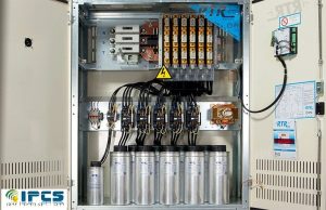
APFC Panels come real handy in the achievement of this purpose. Use of these control panels becomes indispensable in those industries where electrical installations are meant to supply to large electrical load. APFC Panels can effectively and automatically manage quickly changing and scattered loads along with the retention of high Power Factor.
Now we can see how to calculate and choose correct rating capacitor value for any giving value.
For example here we can consider a Single phase 400V, 50Hz, motor, which takes a supply current of 50A at a P.F (Power factor) of 0.6. The motor power factor has to be improved to 0.9 by connecting a capacitor in parallel with it. We have to calculate the required capacity of Capacitor in both kVAR and Farads.
First we need to find the required capacity of Capacitance in kVAR to improve P.F from 0.6 to 0.9
Motor Output = P = V x I x Cosθ
= 400V x 50A x 0.6
= 12kW
Power Factor Correction kVAr = kW (TanΦi – TanΦd)
Φi = Cos-1 of Initial Power Factor Pf
Φd = Cos-1 of Required Power Factor Pf
Actual P.F = Cosθ1 = 0.60
Required P.F = Cosθ2 = 0.90
θ1 = Cos-1 = (0.60) = 53°.13; Tan θ1 = Tan (53°.13) = 1.3333
θ2 = Cos-1 = (0.90) = 25°.84; Tan θ2 = Tan (25°.50) = 0.4843
Required Capacitor kVAR to improve P.F from 0.60 to 0.90
Required Capacitor kVAR = P (Tan θ1 – Tan θ2)
= 12kW (1.3333– 0.4843)
= 10.188 kVAR
We have already calculated the required Capacity of Capacitor in kVAR, so we can easily convert it into Farads by using this simple formula
Required Capacity of Capacitor in Farads/Microfarads C = kVAR / (2 π f V2) in microfarads
Putting the Values in the above formula
= (10.188kVAR) / (2 x π x 50 x 4002)
= 2.0268 x 10-4
= 202.7 x 10-6
= 202.7μF
For improving power factor, electricity consumers have to connect capacitors of optimum rating across inductive load. However the capacitor value needs to be selected according to reactive power. Too low value of capacitors results in inductive power factor, too high value in capacitive power factor. Capacitor panel’s automatically select optimum value of capacitors such that power factor is close to unity.