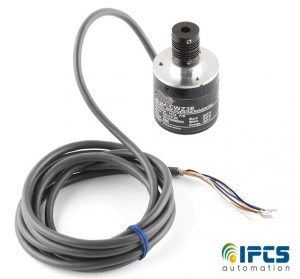
Basics of Encoders
A gadget a circuit, transducer, software program, algorithm or person adapt the form of information from one format or code to another called encoder. In industries using rotary encoders the position of the shaft can be electronically monitored. Absolute encoders and incremental encoders are two types of encoders used in industries. The current shaft position indicated by the output of an absolute encoder. For maintaining position accuracy The system does not need to return to a calibration point. Rotary encoder immediately reports changes in shaft position also it does not report or keep track of absolute position. the mechanical system may have to be moved to a fixed reference point to initialize the position measurement while monitored by an incremental encoder

Encoder topologies
Conductive: For encode the information a PCB is used by a series of circumferential copper tracks etched into it. conductive areas since the Contact brushes. Except as user input in digital multimeters, this form of encoder is now rarely used.
Optical: through slits in a metal or glass disc a light shining onto a photodiode. Reflective versions also exist. Optical encoders are very sensitive to dust. This is one of the most common technologies.
On-Axis Magnetic: This technology typically uses a two pole neodymium magnet which is specially magnetized attached to the motor shaft. Because it can be fixed to the end of the shaft if only one shaft extending out of the motor body it can work with motors. under 1 degree The accuracy can vary from a few degrees. Resolutions can be as high as 0.09 degree or as low as 1 degree.
Off-Axis Magnetic: Rubber bonded ferrite magnets attached to a metal hub is the technology typically used. For custom applications, this offers flexibility in design and low cost. the chip can be placed in any position required for the application Due to the flexibility in many off-axis encoder chips they can be programmed to accept any number of pole widths. optical encoders would fail to work in harsh environments where Magnetic encoders.
Absolute rotary encoder
Mechanical absolute encoders
A metal disc which is rigidly fixed to the shaft containing a set of concentric rings of openings is fixed to an insulating disc, A row of sliding contacts is fixed to a stationary object so that each connection from the shaft wipes against the metal disc at a different distance. some of the contacts touch metal when the disc rotates with the shaft, where the metal has been cut out others fall in the gaps. a source of electric current sheet is connected to a metal, and a separately electrical sensor is connected to each contact. The metal pattern is designed so the axle creates a unique binary code in each possible position. some of the contacts are connected to the current source (i.e. switched on) and others are not (i.e. switched off).
Optical absolute encoders
The optical encoder’s transparent and opaque area in a disc is made of plastic or glass. A light source and photodetector array read the optical pattern that results from the disc’s position at any one time. It often used the Gray code.This code can be read by a controlling device, such the angle of the shaft determine as a microprocessor or microcontroller.
Magnetic absolute encoders
two or more magnetic poles are used in series, Typically magneto-resistive or Hall Effect The magnetic encoder represent the encoder position to a magnetic sensor. The magnetic pole positions are read by the magnetic sensor.The unique dual analog code type produces the absolute analog encoder by using a special algorithm that can be translated into an absolute angle of the shaft. These encoders may be optimal to use in conditions Due to the nature of recording magnetic effects where other types of encoders may fail due to
dust or debris accumulation. Magnetic encoders are also relatively insensitive to vibrations, minor misalignment, or shocks.
Capacitive absolute encoders
Capacitor absolute encoders are used in an asymmetrically shaped disc is rotated within the encoder. This disc will change the capacitance between two electrodes, the change in capacitance which can be measured and calculated convert to an angular value.
Rotary Incremental encoder
Due to its low cost and ability to provide real-time position information the rotary incremental encoder is the most widely used of all rotary encoders. The measurement resolution of an incremental encoder is not limited in any way.
