
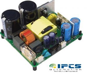
A switched-mode power supply (SMPS) is an electronic circuit that converts power using switching devices that are turned on and off at high frequencies, and storage components such as inductors or capacitors to supply power when the switching device is in its non-conduction state.
Switching power supplies have high efficiency and are widely used in a variety of electronic equipment, including computers and other sensitive equipment requiring stable and efficient power supply.
Switched-mode power supplies are classified according to the type of input and output . The four major categories are:
- AC to DC
- DC to DC
- Forward Converter
- Flyback Converter
- Self-Oscillating Flyback Converter
AC to DC
A basic isolated AC to DC switched-mode power supply consists of:
- Input rectifier and filter
- Inverter consisting of switching devices such as MOSFETs
- Transformer
- Output rectifier and filter
- Feedback and control circuit
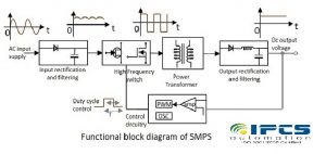
Let us try to understand what happens at each stage of SMPS circuit.
Input Stage
The AC input supply signal 50 Hz is given directly to the rectifier and filter circuit combination without using any transformer. This output will have many variations and the capacitance value of the capacitor should be higher to handle the input fluctuations. This unregulated dc is given to the central switching section of SMPS.
Switching Section
A fast switching device such as a Power transistor or a MOSFET is employed in this section, which switches ON and OFF according to the variations and this output is given to the primary of the transformer present in this section. The transformer used here are much smaller and lighter ones unlike the ones used for 60 Hz supply. These are much efficient and hence the power conversion ratio is higher.
Output Stage
The output signal from the switching section is again rectified and filtered, to get the required DC voltage. This is a regulated output voltage which is then given to the control circuit, which is a feedback circuit. The final output is obtained after considering the feedback signal.
Control Unit
This unit is the feedback circuit which has many sections. Let us have a clear understanding about this from The following figure.
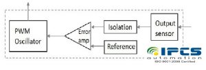
The output sensor senses the signal and joins it to the control unit. The signal is isolated from the other section so that any sudden spikes should not affect the circuitry. A reference voltage is given as one input along with the signal to the error amplifier which is a comparator that compares the signal with the required signal level.
By controlling the chopping frequency the final voltage level is maintained. This is controlled by comparing the inputs given to the error amplifier, whose output helps to decide whether to increase or decrease the chopping frequency. The PWM oscillator produces a standard PWM wave fixed frequency.
By varying the duty cycle or frequency of switching, we can vary the stored energy in each cycle and thus control the output voltage. Higher efficiency is obtained since only the energy required is pumped to maintain the load current hence no power dissipation.
DC to DC
A basic isolated DC to DC switched-mode power supply consists of:
In this power source, a high voltage DC power is directly acquired from a DC power source. Then, this high voltage DC power is switched usually in the range of 15 KHz-5 KHz. And, then it is fed to a step down transformer unit of 50Hz. The o/p of this transformer is fed to the rectifier, them this rectified o/p power is used as a source for loads, and the oscillator ON time is controlled and a closed loop regulator is formed.
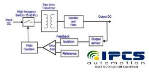
The switching-power supply o/p is regulated by using Pulse Width Modulation shown in the above circuit, the switch is driven by the PWM oscillator, and then indirectly the step down transformer is controlled when the power fed to the transformer. Therefore, the o/p is controlled by the pulse width modulation, as this o/p voltage and PWM signal are inversely proportional to each other. If the duty cycle is 50%, then the max power is transferred through the transformer, and if the duty cycles drops, then the power in the transformer also drops by decreasing the power dissipation.
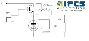
Forward Converter
In a forward converter the choke carries both current both when the transistor is conducting as well as it is not. The diode carries the current during the OFF period of the transistor. Therefore, energy flows into the load during both the periods. The output voltage Vo can only be less than Vs in this circuit. The choke stores energy during the ON period and also passes some energy into the output load. The diode serves two functions.
- It provides a discharge path for the choke so that, when the transistor switches opens, there is no arcing due to the induced high voltage.
- It provides a path for the current in the coil to decay.
Flyback Converter
In the flyback converter, the energy is stored entirely in the magnetic field of the inductor during the ON period of the switch. The energy is emptied into the output voltage circuit when the switch is in the open state. The output voltage depends upon the duty cycle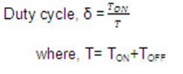
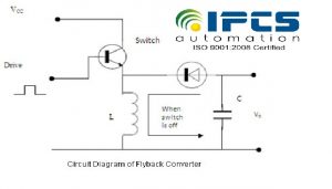
Self-Oscillating Flyback Converter
Self-Oscillating Flyback Converter is the most simple and basic converter based on the flyback principle. A switching transistor, a converter transformer, a fast recovery rectifier and an output filter capacitor make up a complete d.c. to d.c. converter. It is a constant output power converter and so is all other d.c. to d.c. converters based on the flyback principle.
During the conduction time of the switching transistor, the current through the transformer primary starts ramping up linearly with the slope equal to Vin/Lp. The voltage induced in the secondary winding and the feedback winding make the fast recovery rectifier reverse biased and hold the conducting transistor ON.
When the primary current reaches a peak value Ip, where the core begins to saturate, the current tends to rise very sharply. This sharp rise in current cannot be supported by the fixed base drive provided by the feedback winding. As a result, the switching begins to come out of saturation. 
This is a regenerative process with the transistor getting switched OFF. The magnetic field due to the current flowing in the primary winding collapses, thus reversing the polarities of the induced voltages. The fast recovery rectifier is forward biased and the stored energy is transferred to the capacitor and load through the secondary winding. Thus, the energy is stored during the ON time and transferred during OFF time.
The output capacitor supplies the load current during the ON time of the transistor when no energy is being transferred from the primary side. It is constant output power converter. The output voltage reduces as the load increases and vice versa. Utmost care should be taken to ensure that the load is not accidentally taken off the converter. In that case, the output voltage would rise without limit till any of the converter components gets damaged. It is suitable for low power output applications due to its inherent nature of operation and may be used with advantage up to an output power of 150 W. It has high output voltage ripple.
The SMPS is mostly used where switching of voltages is not at all a problem and where efficiency of the system really matters. There are few points which are to be noted regarding SMPS. They are
- SMPS circuit is operated by switching and hence the voltages vary continuously.
- The switching device is operated in saturation or cut off mode.
- The output voltage is controlled by the switching time of the feedback circuitry.
- Switching time is adjusted by adjusting the duty cycle.
- The efficiency of SMPS is high because, instead of dissipating excess power as heat, it continuously switches its input to control the output.
Advantage
- The efficiency is as high as 80 to 90%
- Less heat generation; less power wastage.
- Reduced harmonic feedback into the supply mains.
- The device is compact and small in size.
- The manufacturing cost is reduced.
- Provision for providing the required number of voltages.
Disadvantagees
- The noise is present due to high frequency switching.
- The circuit is complex.
- It produces electromagnetic interference.
- Expensive compared to linear supplies
Applications
There are many applications of SMPS.
- They are used in the motherboard of computers,
- mobile phone chargers,
- HVDC measurements,
- battery chargers,
- central power distribution,
- motor vehicles,
- consumer electronics,
- laptops,
- security systems,
- space stations, etc.
IPCS Automation
We are providing industries with services ranging from proposing and installing to the absolute commissioning of automated system, completely adhering to the industry standards. IPCS provides its customers with a plethora of products- HMI systems, Programmable Logic Controllers (PLCs), DCS systems, Supervisory Control and Data Acquisition (SCADA), drives, sensors, DCS systems and much more. We also offer Lightning and Surge Protection Devices from Dehn, Germany. IPCS aims to avail a definitive intelligent solution for eradicating the energy losses incurred in industries and we have always succeeded in the same. Apart from all these, we conduct numerous training programs in corporate companies and also for professionals in the areas of PLC, SCADA, DCS, HMI, Drives, Embedded, Panel Designing, Process Control, Electric Controls and Industrial Networking. And also we are Providing Building Management System (BMS) Course for the students BMS Course in Chennai.