
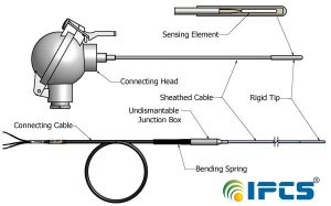
Resistance thermometers change their electrical resistance as a function of temperature. This physical effect makes it possible to measure the temperature of a process with a Pt100. Pt100, Pt1000 are the most-used measuring elements in resistance thermometers and very common sensors in the process industry.
The resistance is determined by electronics (e.g. temperature transmitter) by using a constant current and measuring the voltage drop. According to Ohm’s law (R = U/I), the resistance [R] and voltage [U] are proportional to each other at a constant current [I]. There are three possible ways to connect the Pt100 to the transmitter: in a 2-, 3- or 4-wire connection.
The sensing elements in Resistance Temperature Detectors (RTD’s) can be categorized in terms of the type of metal out of which they’re made and their resistance at a benchmark temperature. A sensor’s name provides information on both of these characteristics.
The RTD PT100, which is the most commonly used RTD sensor, is made of platinum (PT), and its resistance value at 0°C is 100 O. In contrast, a PT1000 sensor, also made of platinum, has a resistance value of 1000 O at 0°C.
The RTD Pt100 and Pt1000 are available in a similar range of tolerances, and both can have similar temperature coefficients, depending on the purity of the platinum used in the sensor. When comparing the Pt100 vs Pt1000 in terms of resistance, keep in mind that resistance value readings for the Pt1000 will be higher by a factor of ten than resistance value readings for the Pt100 at the same temperature. For most applications, the Pt100 and Pt1000 can be used interchangeably depending on the instrument used. In some cases the Pt1000 will work better and be more accurate.
Temperature coefficient
The most common RTD sensor in process industry is the Pt100 sensor, which has a resistance of 100 ohms at 0°C (32°F).
With the same logical naming convention, a Pt200 sensor has a resistance of 200 ohms and Pt1000 has 1000 ohms at 0°C (32°F).
The resistance of Pt100 sensor (and other Pt sensors) at higher temperatures depends on the version of the Pt100 sensor, as there are a few different versions of the Pt100 sensor, which have slightly different temperature coefficients. Globally, the most common is the “385” version. If the coefficient is not mentioned, it is typically the 385.
The temperature coefficient (indicated with Greek symbol Alpha => α) of the Pt100 sensor is indicated as the difference of the resistance at 100°C and 0°C, divided by the resistance at 0°C multiplied with 100°C.
The formula is pretty simple, but it does sound a bit complicated when written, so let’s look at it as a formula:
Alpha formula
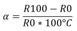
Where:
α = temperature coefficient
R100 = resistance at 100°C
R0 = resistance at 0°C
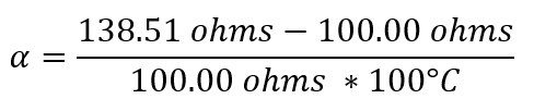
Let’s take a look at an example to make sure this is clear:
Pt100 has a resistance of 100.00 ohms at 0°C and a resistance of 138.51 ohms at 100°C. The temperature coefficient can be calculated by the following:
alpha example picture
We get a result of 0.003851 /°C.
Or as it is often written: 3.851 x 10⁻³ °C-1
Often this is referred and rounded as a “385” Pt100 sensor.
This is also the temperature coefficient specified in standard IEC 60751:2008.
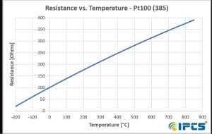
In the graphics below, you can see how a Pt100 (385) sensor’s resistance depends on temperature:
2 wire RTD connections
The 2 wire RTD configuration is the simplest among RTD circuit designs. In this serial configuration, a single lead wire connects each end of the RTD element to the monitoring device. Because the resistance calculated for the circuit includes the resistance in the lead wires and connectors as well as the resistance in the RTD element, the result will always contain some degree of error.
The circle represents the resistance element boundaries to the point of calibration. 3- or 4-wire configuration must be extended from the point of calibration so that all uncalibrated resistances are compensated.
The resistance RE is taken from the resistance element and is the value that will supply us with an accurate temperature measurement. Unfortunately, when we take our resistance measurement, the instrument will indicate RTOTAL:
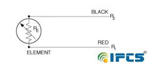
Where
RT = R1 + R2 + RE
This will produce a temperature readout higher than that actually being measured. Many systems can be calibrated to eliminate this. Most RTD’s incorporate a third wire with resistance R3. This wire will be connected to one side of the resistance element along with lead 2.
Although the use of high-quality test leads and connectors can reduce this error, it is impossible to eliminate it entirely A larger gauge wire with less resistance will minimize the error. A 2 wire RTD configuration is the most useful with high-resistance sensors or in applications where a great deal of accuracy is not required.
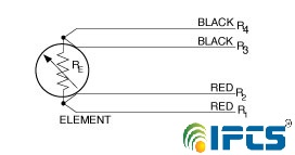
3 wire RTD connections
The 3 wire RTD configuration is the most commonly used RTD circuit design and can be seen in industrial process and monitoring applications. In this configuration, two wires link the sensing element to the monitoring device on one side of the sensing element, and one links it on its other side.

If three identical type wires are used and their lengths are equal, then R1 = R2 = R3. By measuring the resistance through leads 1, 2 and the resistance element, a total system resistance is measured (R1 + R2 + RE ).
If the resistance is also measured through leads 2 and 3 (R2 + R3), we obtain the resistance of just the lead wires, and since all lead wire resistances are equal, subtracting this value (R2 + R3) from the total system resistance (R1 + R2 + RE) leaves us with just RE, and an accurate temperature measurement has been made.
Because this is an averaged result, the measurement will be accurate only if all three connecting wires have the same resistance.
4 wire RTD connections
This configuration is the most complex and thus the most time-consuming and expensive to install, but it produces the most accurate results.
The bridge output voltage is an indirect indication of the RTD resistance. The bridge requires four connection wires, an external source, and three resistors that have a zero temperature coefficient. To avoid subjecting the three bridge-completion resistors to the same temperature as the RTD sensor, the RTD is separated from the bridge by a pair of extension wires:
These extension wires recreate the problem that we had initially: The impedance of the extension wires affects the temperature reading. This effect can be minimized by using a three-wire bridge configuration:
In a 4-wire RTD configuration, two wires link the sensing element to the monitoring devise on both sides of the sensing element. One set of wires delivers the current used for measurement, and the other set measures the voltage drop over the resistor.
With the 4-wire configuration, the instrument will pass a constant current (I) through the outer leads, 1 and 4.
The Wheatstone bridge creates a non-linear relationship between resistance change and bridge output voltage change. This compounds the already non-linear temperature-resistance characteristic of the RTD by requiring an additional equation to convert bridge output voltage to equivalent RTD impedance.
The voltage drop is measured across the inner leads, 2 and 3. So from V = IR we learn the resistance of the element alone, with no effect from the lead wire resistance. This offers an advantage over 3-wire configurations only if dissimilar lead wires are used, and this is rarely the case.
This 4 wire bridge design fully compensates for all resistance found in the lead wires and the connectors between them. A 4 wire RTD configuration is primarily used in laboratories and other settings where great accuracy is necessary.short-image-description
2-wire configuration with a closed loop
Still another configuration, now rare, is a standard 2-wire configuration with a closed loop of wire alongside (Figure 5). This functions the same as the 3-wire configuration, but uses an extra wire to do so. A separate pair of wires is provided as a loop to provide compensation for lead resistance and ambient changes in lead resistance.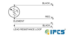
Here’s a closer look at how to determine the difference between Pt1000 vs Pt100:
Pt100
The Pt100 is widely used in many industrial and commercial applications. The Pt100 is better suited to 3 and 4 wire circuit configurations than the 2 wire configuration. This is due to an important Pt100 sensor working principle: because resistance across the sensing element is considerably lower than in the Pt1000, unwanted resistance from lead wires and connectors will have a larger distorting effect on overall resistance measurements, since it will comprise a greater percentage of the total resistance measured in the circuit. The lead wire resistance is measured and compensated for by an instrument that accepts the 3 or 4 wire configurations.
Pt100s are available with both thin-film and wire-wound element constructions. Pt100s are compatible with a broader range of products and instrumentation because their use is so widespread.
Pt1000
Pt 1000 sensors are suitable for use in applications with 2 wire circuit configurations. Since the Pt1000 sensor has much greater resistance, the distorting effect of the resistance in the lead wires is less significant overall because it makes up a smaller percentage of the total resistance in the circuit.
Because a higher resistance value can be measured with less current, Pt1000s can be employed in configurations that consume less power than Pt100s. Power consumption is lower, producing less heat, and thus are less subject to errors caused by self-heating.
When comparing RTD Pt100 vs Pt1000, also keep in mind that Pt1000s are typically available only in thin-film element constructions.