Why Multilevel Inverters?
Two Level Inverter
Basically speaking, an inverter is an electric device that can convert a direct current (DC) to an alternating current (AC). In the normal case, if you consider a two-level inverter simply having an input Vdc, it can provide +Vdc/2, -Vdc/2 as output. Using the PWM Technique, these newly generated voltages are switched thus builds the AC voltage. This method not only creates high harmonic distortion in the output voltage but also has a higher dv/dt when comparing with a multilevel inverter.
Why Multilevel Inverters?
The multilevel inverter is employed in order to achieve high power output voltage with very low harmonic distortion and dv/dt stresses. This is because of its stepped waveform nature of the output. It is achieved by an array of power semiconductor devices and capacitor voltage sources. As the voltage level increases, the smoothness of the waveform increases. Consequently, the complexity of the controller circuit and the components used also increases. Multilevel inverter starts with a three-level inverter. If the number of levels of this inverter increases, the steps in the output waveform also increases which in turn generates a staircase waveform.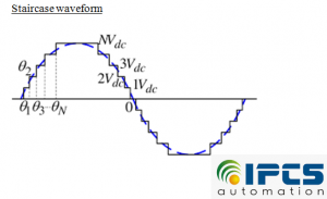
Multilevel Inverters Topology
Different topologies proposed for multilevel inverters are :
- Diode-clamped multi-level inverter
This type of Inverter also known as neutral point converter employs clamped diodes to limit the voltage stresses of power devices. Suppose we have an ‘n-level diode clamped inverter’ then it needs switching devices, input voltage source, and diodes in the order (2n-2), (n-1)and (n-1)(n-2) respectively to operate
- Diode-clamped multi-level inverter
- Capacitor clamped multilevel inverter
The configuration is similar to the previous one except the that here instead of a clamped diode, flying capacitors are used to limit voltage. Suppose we have an ‘n-level capacitor clamped inverter’ then it needs switching devices and capacitors in the order (2n-1) and (n-1) respectively. - Cascaded H-Bridge multilevel inverter
Here several H-Bridge inverters are connected in series to get a sinusoidal output voltage. Different voltages such as V+, V- and 0. Two switching combinations are present for 0 volts are decided by the different combinations of the switching positions. The input DC sources can be any natural resource such as sunlight or wind energy or anything. There are no capacitors or diodes are required for clamping. The output will be a sinusoidal multilevel waveform.
- Capacitor clamped multilevel inverter

About IPCS Automation
IPCS Automation is the largest Automation Course providers in Kerala and also they providing courses in out side part of Kerala. They providing Automation Course in Chennai. IPCS is an ISO certified company and all training program is affiliated by SIDCO (India), IAO (USA), Supreme Education Council (Qatar), TUV Rheinland Germany Certified. Courses PLC Training, Automation Training, BMS Training, CCTV Training, EMBEDDED Training, DCS Training,