Encoder Working Principle:
The Optical Encoders typically consist of a rotating and a stationary electronic circuit. The rotor is usually a metal, glass, or a plastic disc mounted on the encoder shaft. The disc has some kind of optical pattern, which is electronically decoded to generate position information.The rotor disc in absolute optical encoder uses opaque and transparent segments arranged in a Gray-code pattern. The stator has corresponding pairs of LEDs and phototransistors arranged so that the LED light shines through the transparent sections of the rotor disc and received by photo-transistors on the other side. After the electronic signals are amplified and converted, t are then available for the evaluation of the position.

What does the word encoder mean?
The encoder is an electromechanical device that can measure displacement.Encoders are normally digital displacement transducers, consisting of a mechanical element and a sensing head, typically of the optical type. The mechanical element can be a disc (for rotary type encoders) or a ruler (for linear type encoders) with deposited or carved patterns. The sensing head includes a light source (LED) and a light sensor (photodetector) to read the generated code (the encoder output).What different types of encoders exist?
The most widely used classification refers to the type of movement (linear or rotary). In both cases, they can be incremental, semi-absolute or absolute.Incremental information is obtained by simply counting the pulses. Therefore, it depends on the previous state and the value of the transition. Its biggest drawback consists in the need for defining a starting position reference: this information is lost whenever the system is powered down or is turned off.In contrast, in absolute encoders (of angular or linear type) each position is properly referenced with a unique code, Figure 1, corresponding to a unique pattern of bits in the various tracks. So, the position is always known and it is not necessary to define a reference if the system is powered down or is turned off.

Figure 1. The transformation in physical quantities – Gray code encoder.
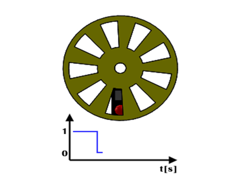

Figure 2. Code wheel and optical sensor examples.


Figure 3. Time evolution of the digital electrical signal.
Figure 3 shows a rotating encoder and the graph represents the time evolution of the digital electrical signal: a rectangular wave sequence of high and low levels, as light reaches the sensor or is blocked.What different types of encoders exist?
With this encoder, the displacement is obtained by counting the number of times that transitions occur between logical values “0” and “1”. This allows the transformation of physical quantities by converting the angular displacement variations into electrical type signal output that is translated into logical values by suitable electronics.The counting of the number of transitions that occur in the (reflective/opaque and non-reflective / transparent) disc sectors is related to the concept of resolution.The resolution may be defined as the smallest change in a quantity under measurement that causes a noticeable change in the corresponding outcome. In this case, the resolution of the disc corresponds to its minimum angular variation that causes a transition at the logical output level. As there are nine 0 to 1 transitions in a complete rotation of the disk in Figure 3, its resolution is 360° / 9 = 40°. So the 40° value matches the period of the blue wave shown in Figure4.
How can we detect the direction of disc rotation?
This solution with only a sensing head is not able to identify the direction of disc rotation. To solve this problem another optical sensing head is used, with its output signal offset from the first by 90°; in other words, the optical sensing head signals are in quadrature. This layout produces two square waves in quadrature, corresponding each to one sensing head (channels A and B), as shown in Figure 4.
Where are they applied?
The incremental rotary encoders are widely used in,- Aerospace
- Material Handling
- Mobile Equipment
- Packaging
- Textiles
- Timber Products
- Converting
- Metal Forming & Fabrication
- Food & Beverage
- Printing