When do you use a PID controller?
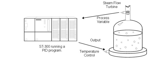
Figure shows a picture of an example system to which a user might connect a PID controller. The figure shows a water tank sitting atop a hot plate, with a temperature control device for the hot plate and a small, monitored turbine for measuring the rate of the steam flow. This is a system that will work with a PID controller because of the relationship between the two variables: You can directly control the steam flow rate by adjusting the temperature of the hot plate. The variable which represents the state of the system being controlled is called the ‘Process Variable.’ In our example above, you can see that the rate at which the steam spins the turbine is a good indicator of the event that we are trying to control: the speed at which the water is being boiled off. The output is the variable which, being altered by the controller, can affect the process variable by different degrees based on its intensity — By turning the hot plate up, the water boils more quickly, more steam is produced, and the turbine’s speed increases. Therefore, when a variable that accurately reflects the state of the process and an adjustable control which proportionally affects the process variable, then it is possible to use a PID controller. Common systems using PID controllers are air conditioning systems, solution mixing, heaters, etc.
Auto Mode vs. Manual Mode: There are two settings available on our PID controller. Putting a controller in Manual mode causes the PID loop do nothing, so that the user can directly control the output. The second, Auto, is the mode in which the PID loop is actually controlling the system. For the rest of this text, it will be assumed that the controller is in Auto mode.
What does the PID controller do, and how does it do it?
Quite simply, a PID controller adjusts the value of its output to try and balance the value of the process variable to a given ‘set point’ .To calculate the output value for a given instance, the controller finds the value of three different terms (using its user defined Sample time, Gain, Rate, and Reset values along with the calculated Error value): a Proportional term, an Integral term, and a Derivative term Output = MP+ MI+ MD
What are the Sample, Gain, Rate, and Reset, and where do they come from?
The sample rate is the cycle time (in milliseconds) at which the PID loop recalculates the output. The gain controls the sensitivity of the output calculation by affecting the influence of all the terms. The reset is a time given in milliseconds which is used to increase or decrease the influence of the Integral term in the equation. Finally, the rate value is used to control the influence of the Derivative term in the equation. Each of these values needs to be preset by the user before the PID controller starts. If the user does not want integral action (no I in the PID calculation), then a value of infinity or a value of 0 should be specified for the integral time. If the user does not want derivative action (no D in the PID calculation), then a value of 0 should be specified for the derivative time. If the user does not want proportional action (no P in the PID), then a value of 0 should be specified for the gain (gain is normally a multiplier in the integral and derivative coefficient calculation, but is removed from the coefficient calculation, if gain = 0, to allow I, ID, or D loop control).
How is the Error figured?
Error is figured as the difference between the normalized values of the set point and the process variable. The controller calculates this value in three steps. The first two steps are to change both the set point and the process variable into values that are based on a 0 to 1 (normalized) scale. This is done using the formulae: SP = raw_SP / max_val PV = raw_PV / max_val In the above formulae, the raw_SP and raw_PV values are the actual values that come into thecontroller, and the max_val term is the maximum value that either can take on. For example, if the values of raw_SP and raw_PV were being read in as values from 0 to 27,648, then the max_valterm would have the value 27,648 After these two values have been calculated, the error term is figured as follows: Error = SP – PV
How is the Proportional term calculated?
The proportional term, MP, is calculated using the following equation MP= Gain* Error Going back to our earlier example with the water tank, the proportional term says that as the speed of the turbine increases further above the set point, the heat is decreased proportionally to bring the speed down. As the turbine slows below the setpoint, the heat is increased to proportionally to bring the speed up.
More News & Events on www.ipcsautomation.com
PLC SCADA VFD HMI DCS TRAINING