In Industrial Automation, generally when people say ‘interposing relay’ it means a general purpose relay that is used for interposing, meaning to separate or put a barrier between two circuits. Interposing relay normally consists of a coil that is energized by either AC or DC power and activates contacts that are used to trigger another circuit.
Interposing relays are semiconductor/electromagnetic relays used to send / receive digital signal ( by contact changeover) through hardwired systems. This is typically done in automation for the following reasons:-
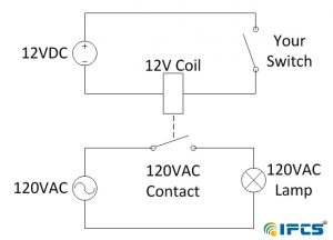
If the two systems are at different voltage rating (as shown above). Here the DC relay (controlled by PLC/ DCS) can be used to turn on and off a device of higher power rating and voltage requirement.
If Isolation is required between 2 systems for safety/protection purpose. If 2 systems are functionally isolated it is preferred that no disturbance propagates from one to other. For eg in power plants Boiler and Turbine panel exchange some critical signals via hardwire. If a voltage fluctuation propagates from one system to other it can increase the already critical situation. Hence isolation is required.
An industrial example of an interposing relay between mismatched devices is shown here, where a DC output proximity switch must trigger an input channel to a Programmable Logic Controller (PLC) rated for 120 volts AC:

Again, the relay in this system performs no logic function, but merely allows the proximity switch to drive one of the PLC input channels.
Directly connecting the proximity switch to one of the input channels of the PLC is not a practical option, because this particular PLC input requires 120 volts AC to activate, and our proximity switch operates on 24 volts DC.
The mismatch between switch voltage and PLC input voltage requires us to use the relay to “interpose” between the switch and PLC.
When the proximity switch senses an object nearby, its output activates, which in turn energizes the relay coil. When the relay contact magnetically closes, it completes a circuit for 120 volts AC to reach input channel 0 on the PLC, thereby energizing it.
An important detail in this relay circuit is the inclusion of a commutating diode in parallel with the relay coil, the purpose being to dissipate the coil’s stored energy upon de-energization when the proximity switch turns off.
Without this diode in place, the coil’s “kickback” voltage (which may reach hundreds of volts in potential) will destroy the proximity switch’s output transistor.
Note how this commutating diode appears to be connected “backwards” with regard to the polarity of the 24 volt DC power source: cathode toward the source’s positive pole and anode toward the source’s negative pole.
This is intentional, as we do not wish to have the diode conduct when power is applied to the relay coil through the proximity switch (If the diode were connected the other way, it would pass current whenever the proximity switch turned on, shorting past the relay coil and most likely damaging the proximity switch in doing so!).
The diode only turns on when the polarity reverses, which is what happens when the proximity switch turns off and the relay coil’s magnetic field collapses (now acting as a source rather than as a load).
As the relay coil temporarily outputs a “reverse” voltage, the diode gives that coil a continuous path for its current while dropping a low voltage (about 0.7 volts DC), dissipating the coil’s stored energy in the form of heat at the diode.
Interposing relays are also used to connected mismatched PLC outputs and control devices. In this application, the mismatch may be in terms of voltage ratings and/or current ratings.
As with the input interposing circuit shown previously, the task of the relay in an output interposing circuit is to be controlled by the PLC’s output channel, and in turn direct power to a field device that is itself incompatible with the PLC’s output.
The following diagram shows an example of an interposing relay connected to a PLC output channel:
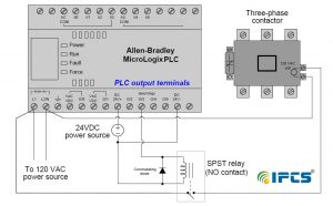
In this circuit the PLC’s transistor outputs can only handle 24 volts DC, and at fairly low current. The three-phase contactor coil requires 120 volts AC at modest current levels to function, and so the relay interposes between the PLC’s low-voltage and low-current output channel and the relatively high-voltage and high-current demands of the contactor’s coil.
Once again we see the use of a commutating diode to dissipate the relay coil’s stored energy whenever the PLC de-energizes it, so that the resulting “kickback” voltage does not damage the fragile transistor output circuitry within the PLC.