Difference Between RS232 RS422 and RS485 RS232 vs RS422 vs RS485 serial interfaces:
This topic process on RS232 vs RS422 vs RS485 describes the difference between RS232, RS422, RS485 serial interfaces. The difference between various terms and serial interfaces are also mentioned. All these are known as serial interfaces used for transmission of data at short distances. These interfaces are most popular for monitoring and control applications.
RS232 interface:
Before the introduction of USB and PS2 interfaces, RS232 interface was very popular for connecting mouse, modem and printer with the computer. RS232 is a single-ended serial interface which allows one transmitter and one receiver to be connected together for transfer of data.
On DB9 connector pin numbers 2 is RxD and 3 is TxD and hence in order to connect two devices interface cables need to have following cross connections.
1 (DB9) <——–> (DB9)
2 (RxD)<——–> 3(TxD)
3 (TxD)<——–> 2 (RxD)
On DB25 connector pin numbers are 2(TD) and 3(RD). Hence following wiring connection need to be made to connect RS232 DB9 with DB25 connector.
1 (DB9) <——–> (DB25)
2 (RxD) <——–>2 (TD)
3 (TxD) <——–> 3 (RD)
RS232 interface uses full duplex method of transmission. It can transfer data at the rate of 1 Mbps to a maximum distance of about 50 feet.
RS232 interface Features:
Cabling technique: single ended
Communication mode: Full duplex
No. of devices: 1 transmit and 1 receive
Maximum distance: 50feet at 19.2 Kbps rate
Maximum data rate: 1Mbps up to 50 feet distance
Mark (Data ‘1’): -5V min. and -15V max.
Space (Data ‘0’): 5V min. 15V max.
Signaling: unbalanced
RS-232 serial interface:
RS232 is the interface mainly used for serial data communication. It supports data transfer rate from about 110bps to about 115200 bps (bits per sec). Hyper terminal is the application mainly used to check serial communication port of the computer, often referred to as COM port. The interface is two types DB9 and DB25 pin connectors. The interface is mainly used for one to one serial communication for example computer to dial-up modem connection.
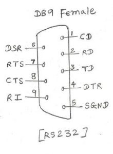
Figure-1 depicts RS232 pin diagrams for DB9 connector.
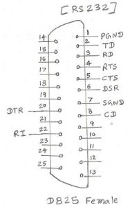
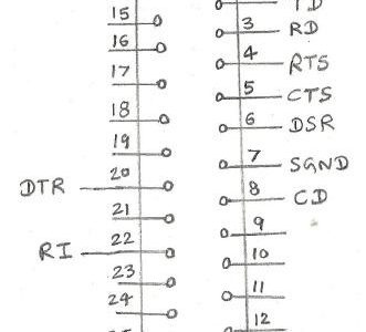
Figure – 2 depicts RS232 pin diagrams for DB25 connector.
As shown in the figure, it carries both data and control signal lines. These are mentioned below.
RD- Receive data, it receives data from DCE (Data communication Equipment) and passes to DTE (Data Terminal Equipment). For example, DTE is the computer and DCE is the modem connected to the telephone line.
TD- Transmit data, it carries data from DTE to DCE.
CD- Carrier Detect, a signal from DCE to DTE. Indicates that modem (DCE) is busy i.e. already using the line.
RI- Signal from DCE to DTE, Modem (DCE) detects ring from the line.
RTS- Request to Send, DTE requests DCE to become ready to accept the data.
CTS- Clear to Send, DCE acknowledges DTE that I am ready to receive the data. (Response of RTS).
DTR- Data Terminal Ready, DTE is ready to transmit.
DSR- Data Set Ready, DCE is ready to receive.
SGND- Signal Ground.
RS232 protocol:
Following are the RS232 protocol details.
• Binary 0 range from about +5 to +15 voltage (DC)
• Binary 1 range from about -5 to -15 voltage (DC)
• Start bit – Binary 0
• Data- 5, 6, 7 or 8 bit configurable
• Parity- Odd/even, is not used with 8 bit of data.
• Stop bit: Binary 1, one or two bits

RS232 technical specifications:
The Table-1 below mentions RS232 interface technical specifications.
| Specifications | RS232 |
| Mode of operation | Single-ended |
| Number of drivers/receivers on one line | 1 driver, 1 receiver |
| Maximum cable length | 50 feet |
| Maximum data rate | 460kbps |
| Max. driver output voltage | +/- 25 V |
| Max. driver current in high impedance state | +/-6mA at +/-2V |
| Slew rate(max) | 30 V/µS |
| receiver input voltage range | +/-15V |
| Receiver input sensitivity | +/-3V |
| Driver load impedance | 3K to 7K Ohms |
| Receiver Input Resistance | 3K to 7K Ohms |
RS-422 interface:
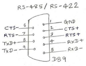
Figure – depicts RS 422 pin configuration for 9 pin connector.
This interface is similar to the RS485 interface. The RS422 interface is used for multidrop configuration and supports up to 10 devices at a time. It is used in balanced differential mode. It supports data rate from 100 kbps to about 10 Mbps.
RS422 Technical Specifications:
Following Table-1 describes RS422 technical specifications.
| Specifications | RS422 |
| Mode of operation | Differential |
| number of drivers/receivers on one line | 1 driver, 10 receiver |
| maximum cable length | 4000 feet |
| maximum data rate | 10 Mbps |
| max. driver output voltage | -0.25V to +6V |
| Max. driver current in high impedance state (power off) | +/-100 µA |
| receiver input voltage range | -10V to +10V |
| Receiver input sensitivity | +/-200mV |
| Driver load impedance | 100 Ohms |
| Receiver Input Resistance | 4K min. |
RS485 interface:

Figure – describes RS485 pin diagram for 9 pin connector.
Tx+ and Tx- carry transmit data and Rx+ and Rx- carry receive data. Due to differential signals distance carried by signals are more.
The RS485 interface supports a higher data rate and distance compared to RS232. It supports a distance of 10 meters for 30-35 Mbps and 1200 meters for the data rate of about 100 kbps. It is a balanced differential interface used mainly for multi-drop configuration. Figure-1 depicts pin configurations of RS485 interface in a 9 pin DB9 connector.
As shown in the pin diagram, RS485 has all the signals in differential configurations.
RxD+ and RxD- used for receiving data
TxD + and TxD- used for transmitting data
CTS + and CTS- as well as RTS+ and RTS- are used as handshake control signals
In a multi-drop configuration, about 32 devices can be connected with 1 master controlling device. One of the application is VSAT NMS (Network Management System) wherein software application running on one PC is used to monitor & control many subsystems. These subsystems are Modems, MUXs, RF upconverters, RF down converters and more. All the subsystems and PC housing NMS software should have RS485 connectors with cable wiring properly done to make this multi-drop configuration work properly.
RS485 Technical Specifications:
Following Table-1 describes RS485 technical specifications.
| Specifications | RS485 |
| Mode of operation | Differential |
| number of drivers/receivers on one line | 1 driver, 32 receiver |
| maximum cable length | 4000 feet |
| maximum data rate | 30 Mbps |
| max. driver output voltage | -7V to +12V |
| Max. driver current in high impedance state (power off) | +/-100 µA |
| receiver input voltage range | -7V to +12V |
| Receiver input sensitivity | +/-200mV |
| Driver load impedance | 54 Ohms |
| Receiver Input Resistance | >=12 K Ohm |