BASIC RULES FOR LADDER DIAGRAM LANGUAGE
BASED PLC PROGRAMMING
We know that PLC supports many programming languages which of that are defined by the International Electro-technical Commission. Ladder diagram Programming language is commonly used for PLC programming and most PLC Programming software supports it. However, We want to know the basics rules before entering into Ladder diagram programming, We will discuss about the basics rules of Ladder Diagram language based PLC Programming not addressing and data types. These are different for every PLC.
Rule No 1: Understand the Structure of Ladder Diagram
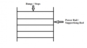
The ladder structure is not different and difficult one to understand. Let us consider a normal ladder, that helps us to pick up things that are are out of reach, our programming has the same ladder structure. This ladder programming also helps us to solve complex problems in plc programming. Normal ladder contains two main parts those are
- Supporting rod
- Step

Diagram – Rule No 1
In ladder programming structure we called power rail and rungs instead of supporting rod and steps.
Rule No 2: Basic components in Ladder Diagram
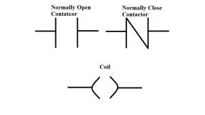
In the ladder programming two major component categories are there
- Contactor
- Coil
Contacts are classified into two types, those are
- Normally open contact
- Normally closed contact
Rule No 3: Basic components place in Ladder Diagram
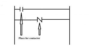
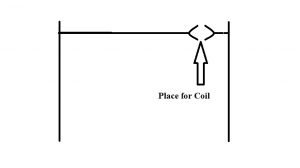
Contact or coil we have no other options those are must place in rungs. But which one has to be placed first contact or coil? The coil can only be placed in the right side of the rung corner. We don’t have permission to place on mid and left side of the rung. We could place contract in the mid and left side in the rung.
Rule No 4: Inputs and outputs are in ladder diagram
We develop program based on a process. The process sequences are defined by their inputs and outputs. So we want to represent each input and output in the programming. So ow to represent? We could assign a coil only as an output. But contact accepts both input and output representation in ladder diagram. A single input perform as a normally open contact and normally closed contact in ladder diagram. We can use a single input name for multiple contacts both normally open and normally closed. A single output primarily performs as a coil. You want output to perform as a contact first you must assign one coil in the same output name. The single output name is only for that single coil. If we assign same name for two or more coils that’s not an error, but we may face some problem in our process sequence.
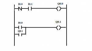
Rule No 5: Series and Parallel Connection in Ladder Diagram
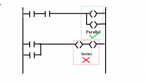
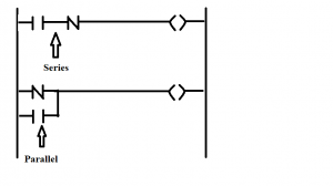
In Ladder Diagram we could place contacts (Normally open & normally Closed) in parallel and series connection. Coils are placed only in Parallel. But some ladder programming software’s offer special instructions for coil series connection.
Prepared By
Bhaskarapratheep Rajendran
Project Engineer
IPCS Automation – Coimbatore
Follow us
![]()
![]()
![]()

