A circuit is a closed conducting path through which an electrical current either flows or is intended to flow. A circuit consists of active and passive elements.

Parameters are the various elements of an electrical circuit (for example, resistance, capacitance, and inductance).
RESISTANCE:

CAPACITANCE:


INDUCTANCE:
 Linear circuit – a circuit in which the parameters are constant with time, do not change with voltage or current, and obey Ohm’s law. In a non-linear circuit the parameters change with voltage and current.

- A passive network is a one which contains no source of EMF.
- An active network is one which contains one or more sources of EMF.

- A bilateral circuit is one whose properties or characteristics are the same in either direction of the current. Example: the usual transmission line is bilateral.
- A unilateral circuit is that circuit in which properties or characteristics change with the direction of operation. Example: a diode rectifier can rectify only in one direction.

- A Node is a point in a circuit where two or more circuit elements are connected together.
- A branch is a part of a network. which lies between two nodes.
- Loop is a closed path in a circuit in which no element or node is encountered more than once.

- Mesh is a loop that contains no other loop within it.
THEOREMS:
OHM’S LAW
Ohm’s law states that the current through a conductor between two points is directly proportional to the voltage across the two points.
V=IR
Where V=voltage,
I=Current,
R=Resistor.

KIRCHOFF’S CURRENT LAW:
Kirchhoff’s Current Law states that: The algebraic sum of currents at a node is zero.

I1 + I2 = I3 + I4
The above equation is showing that current flowing into the node is equal to the current flowing out.
KIRCHOFF’S VOLTAGE LAW:
The algebraic sum of voltages around a closed circuit loop is zero.
V1 + V2 = V3 + V4

Thevenin’s Theorem
Thevenin’s Theorem states that “Any linear circuit containing several voltages and resistances can be replaced by just one single voltage in series with a single resistance connected across the load“.

- Thevenin’s Theorem is a way to reduce a network to an equivalent circuit composed of a single voltage source, series resistance, and series load.
Steps to follow for Thevenin’s Theorem:
(1) Find the Thevenin source voltage by removing the load resistor from the original circuit and calculating voltage across the open connection points where the load resistor used to be.
(2) Find the Thevenin resistance by removing all power sources in the original circuit (voltage sources shorted and current sources open) and calculating total resistance between the open connection points.
(3) Draw the Thevenin equivalent circuit, with the Thevenin voltage source in series with the Thevenin resistance. The load resistor re-attaches between the two open points of the equivalent circuit.
(4) Analyze voltage and current for the load resistor following the rules for series circuits.
NORTONS THEOREM
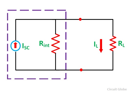
Norton’s Theorem states that – A linear active network consisting of an independent or dependent voltage source and current sources and the various circuit elements can be substituted by an equivalent circuit consisting of a current source in parallel with a resistance. The current source being the short-circuited current across the load terminal and the resistance being the internal resistance of the source network.


Where,
- IL is the load current.
- Isc is the short circuit current.
- Rint is the internal resistance of the circuit.
- RL is the load resistance of the circuit.
Steps for Solving a Network Utilizing Norton’s Theorem
Step 1 – Remove the load resistance of the circuit.
Step 2 – Find the internal resistance Rint of the source network by deactivating the constant sources.
Step 3 – Now short the load terminals and find the short circuit current ISC flowing through the shorted load terminals using conventional network analysis methods.
Step 4 – Norton’s equivalent circuit is drawn by keeping the internal resistance Rint in parallel with the short circuit current ISC.
Step 5 – Reconnect the load resistance RL of the circuit across the load terminals and find the current through it known as load current IL.
Thevenin and Norton Equivalence
- Thevenin and Norton’s resistances are equal.
- Thevenin voltage is equal to Norton’s current times Norton resistance.
- Norton current is equal to Thevenin voltage divided by Thevenin resistance.
Superposition Theorem
- The Superposition Theorem states that a circuit can be analyzed with only one source of power at a time, the corresponding component voltages and currents algebraically added to find out what they’ll do with all power sources in effect.
- To negate all but one power source for analysis, replace any source of voltage (batteries) with a wire; replace any current source with an open (break).

Steps for Solving a Network Utilizing Superposition Theorem
Step 1 – Take only one independent source of voltage or current and deactivate the other source.
Step 2 – In the circuit diagram B shown above, consider the source E1 and replace the other source E2 by its internal resistance. If its internal resistance is not given, then it is taken as zero and the source is short-circuited.
Step 3 – If there is a voltage source than a short circuit it and if there is a current source than just open circuit it.
Step 4 – Thus, by activating one source and deactivating the other source find the current in each branch of the network. Taking the above example find the current I1’, I2’and I3’.
Step 5 – Now consider the other source E2 and replace the source E1 by its internal resistance r1 as shown in the circuit diagram C.
Step 6 – Determine the current in various sections, I1’’, I2’’ and I3’’.
Step 7 – Now to determine the net branch current utilizing the superposition theorem, add the currents obtained from each individual source for each branch.
Step 8 – If the current obtained by each branch is in the same direction then add them and if it is in the opposite direction, subtract them to obtain the net current in each branch.
The actual flow of current in the circuit C will be given by the equations shown below,

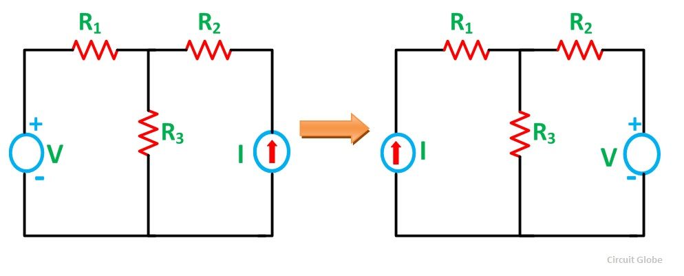
Reciprocity Theorem
Reciprocity Theorem states that – In any branch of a network or circuit, the current due to a single source of voltage (V) in the network is equal to the current through that branch in which the source was originally placed when the source is again put in the branch in which the current was originally obtained. This theorem is used in the bilateral linear network which consists of bilateral components.

Steps for Solving a Network Utilizing Reciprocity Theorem
Step 1 – Firstly, select the branches between which reciprocity has to be established.
Step 2 – The current in the branch is obtained using any conventional network analysis method.
Step 3 – The voltage source is interchanged between the branches which are selected.
Step 4 – The current in the branch where the voltage source was existing earlier is calculated.
Step 5 – Now, it is seen that the current obtained in the previous connection, i.e., in step 2 and the current which is calculated when the source is interchanged, i.e., in step 4 are identical to each other.
Compensation Theorem
Compensation Theorem states that in a linear time-invariant network when the resistance (R) of an uncoupled branch, carrying a current (I), is changed by (ΔR). The currents in all the branches would change and can be obtained by assuming that an ideal voltage source of (VC) has been connected such that VC = I (ΔR) in series with (R + ΔR) when all other sources in the network are replaced by their internal resistances.


Millman’s Theorem
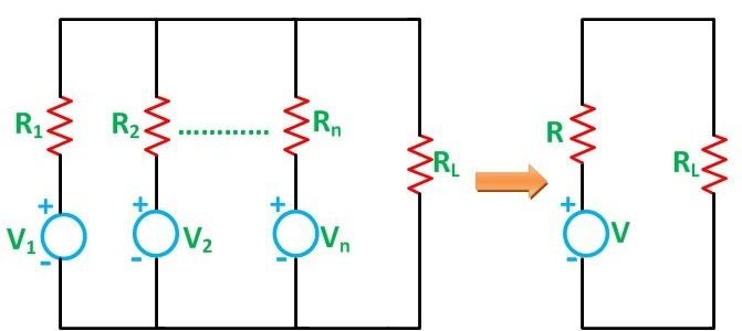
The Millman’s Theorem states that – when a number of voltage sources (V1, V2, V3……… Vn) are in parallel having internal resistance (R1, R2, R3………….Rn) respectively, the arrangement can replace by a single equivalent voltage source V in series with an equivalent series resistance R. In other words; it determines the voltage across the parallel branches of the circuit, which have more than one voltage sources, i.e., reduces the complexity of the electrical circuit.

Joule’s Law
Joule’s Law states that H (Heat) = I (Current) x V (Voltage) x T (Time the current is allowed to flow).
Or
H (Heat) = I2 (Current squared) x R (Resistance) x T (Time the current is allowed to flow).
Maximum Power Transfer Theorem
The Maximum Power Transfer Theorem states that the maximum amount of power will be dissipated by a load resistance if it is equal to the Thevenin or Norton resistance of the network supplying power.
Maximum Power Transfer is calculated by the equation shown below,


