There is much doubt on this topic PTO and PWM. The Engineers using μ -controllers refer to Pulse Width Modulation regardless, if it is PTO or PWM. For PLCs it is important to know the difference. The automation training in kochi helps out in the working of PTO and PWM.
For motion control the PWM and PTO are setting an analog SP. Speed and position can be controlled via this digital transmission method. A Programmable Logic Control output is assigned to use PWM or PTO; not both. Only specific o/p s are detached for the function.
PWM (Pulse Width modulation)
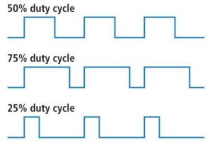
When the signal goes high, we call this “ON time”. To explain the total amount of “ON time” is called duty cycle and the duty cycle is measured in %. The percentage duty cycle specifically explain the % of time a digital signal is ON over an interval of time. This pulse duration is the inverse of the frequency of the waveform.
If a digital signal spends 1/2 of the time ON and the other 1/2 OFF, we say the digital signal has a duty cycle of 50% and resembles an ideal square wave. If the percentage is higher than 50%, the digital signal spends more time in the high state than the low state and vice versa if the duty cycle is less than 50%. Here is a graph that illustrates these three scenarios
50%75% and 25% Duty Cycle Examples
100% duty cycle would be the same as setting the voltage to 5 Volts (high). 0% duty cycle would be the same as grounding the signal (0Volt).

- Changes of Duty Cycle while frequency stays a fixed value.
- T (period) is fixed while it is being used. Normally settled by hardware, but can be varied by software – not while pulsing.
- The ratio of T (off) to T (on) can be varied by the software.
- Motion control: DC motor amplifier cards are used to provide a set point (SP). The change in duty cycle can be sieve to an analog ckt that does not use μ -controller processing.
- Propagation Integral and Derivative loop control can give PWM output. As another option a user program use it as if an analog output which vary the PWM duty cycle. It is speed control only.
PTO (Pulse Train Output)
PTO is for accurate positioning or precise velocity-control. A pulse rotates the motor by a fractional amount.
- Changing of frequency while duty cycle remains at 50%.
- T (duration) is varied. The control is done from software.
- The ratio of T (OFF) to T (ON) can be fixed at 50%:50%.
- Motion control: The open loop control of stepper motor the stepper motor amplifier ensures a constant distance increment for each pulse received. The duration of the increment is given by the frequency of the pulse. This is more familiar to use than PWM, used for stepper motors and servo motors. Position and speed can be controlled even if only open loop control is used.
- The Programmable Logical control provides for motion control. With the S7-1200 FW4.2 a new block is available that can set the frequency. A user program can manipulate directly the frequency. This is helpful for working speed control of variable speed drives instead of using analog control. Not helpful for steppers/servos.

